

close
Choose Your Site
Global
Social Media
Views: 0 Author: Site Editor Publish Time: 2026-09-26 Origin: Site


Transferring Liquefied Natural Gas (LNG) at -162°C (-260°F) introduces extreme thermal stress and massive material contraction. Standard equipment simply cannot survive these brutal conditions. Severe safety liabilities define this harsh operational reality.
Failures in low temperature fluid transfer lead directly to catastrophic leaks and highly hazardous environments. They also generate excessive Boil-Off Gas (BOG). These critical failures trigger severe terminal downtime. Such disruptions risk both operational integrity and overall site safety.
This guide provides engineering and procurement teams a rigorous, evidence-based evaluation framework. You will discover how to specify and select a robust Cryogenic LNG Loading Arm for your exact facility layout. We reveal how you can effectively balance stringent safety compliance alongside sustainable operational longevity.
Seal Integrity is paramount: Dynamic rotational movement at cryogenic temperatures requires specialized materials like PCTFE to prevent catastrophic leaks.
Demand empirical validation: Shortlist suppliers who provide rigorous Finite Element Analysis (FEA) for thermal stress and fluid dynamics.
Safety systems are non-negotiable: Integration of Emergency Release Systems (ERS) and nitrogen purging dictates the baseline for terminal safety.
Customization reduces OPEX: Off-the-shelf solutions often fail; custom LNG equipment tailored to specific drift, surge, and footprint allowances lowers total cost of ownership.
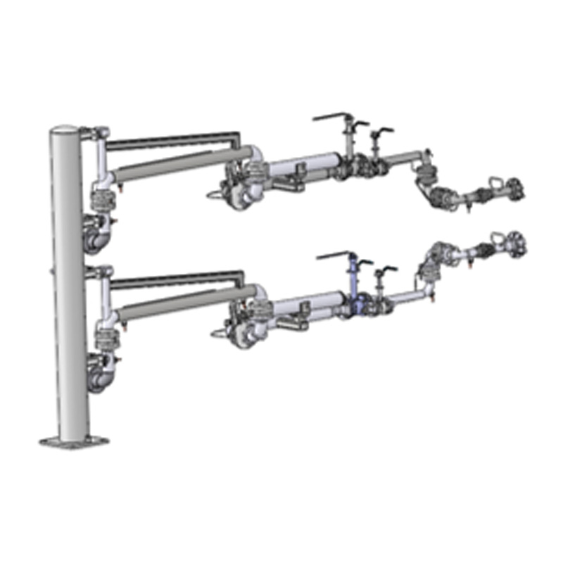
The sudden temperature drop during the initial chill-down phase aggressively stresses structural integrity. Piping undergoes rapid thermal contraction across its entire length. If you ignore this physical movement, pipeline supports inevitably fail. The resulting stress fractures can compromise the entire transfer network.
Atmospheric moisture constantly threatens articulation points in outdoor terminal environments. Ice accumulates rapidly when ambient moisture freezes directly on the swivel joints. This creates severe mechanical resistance during routine operations. Operators often apply excessive hydraulic force to compensate for stiff joints. This daily struggle accelerates structural fatigue over time. You risk premature mechanical failure if ice buildup persists.
Inefficient heat transfer insulation dramatically worsens Boil-Off Gas (BOG) generation. High BOG volumes create massive financial losses per loading cycle. They also trigger critical safety alarms across the terminal network. You must manage heat ingress efficiently to keep terminal pressure stable.
Procurement teams frequently fixate on base unit pricing during the bidding process. This narrow evaluation lens creates hidden downstream vulnerabilities. You should intentionally shift your focus toward failure-rate probability. Prioritize thermal cycling endurance above initial hardware expenses. A cheaper unit costs exponentially more when it halts terminal operations.
Extreme cold rapidly degrades standard carbon steel structures. You must mandate Austenitic stainless steels for all pressure-containing components. Grades like 316 and 316L prevent catastrophic low-temperature embrittlement. These specific alloys maintain their vital ductility even at -162°C.
Design validation requires comprehensive testing documentation from the manufacturer. A reliable liquefied gas loading arm needs exhaustive low-temperature heat transfer reports. Manufacturers must provide rigorous Finite Element Analysis (FEA). These complex analytical reports prove structural reliability under severe dynamic loads. They simulate real-world wind forces, liquid weight, and thermal contraction simultaneously.
Dynamic sealing dictates long-term system reliability. Polychlorotrifluoroethylene (PCTFE) remains the undisputed industry standard for cryogenic seals. It offers superior dimensional stability in extreme freezing conditions. PCTFE also exhibits exceptionally low cold-flow characteristics under high mechanical pressure.
Continuous rotational movement severely challenges swivel joint integrity. The dynamic sealing architecture must maintain a flawless leak-tight barrier. It performs this duty during intense thermal contraction. Swivel joints endure immense lateral stress while compensating for constant vessel drift.
Maintenance accessibility directly impacts your annual operational uptime. Assess the swivel joint design for practical in-situ seal replacement capabilities. Technicians should perform field repairs without utilizing heavy lifting equipment. You never want to dismantle the entire arm for a simple seal swap.
Operational emergencies demand immediate and reliable separation capabilities. Emergency Release Couplers (ERC) provide critical double-valve dry-break functionality. They ensure an immediate, spill-free disconnection during abnormal vessel drift scenarios. They also activate automatically during sudden line pressure anomalies.
Automation safety systems require stringent industrial classifications. Sensors, visual alarms, and hydraulic actuation systems must meet specific Safety Integrity Levels (SIL). We highly recommend integrating SIL-rated components throughout the control panel. This integration easily satisfies the demanding standards of modern petrochemical facilities.
Marine loading environments introduce highly unpredictable environmental variables. Engineers must carefully account for severe tidal variations and intense wind loads. Unpredictable ship drift severely complicates the precise connection geometry.
LNG terminal equipment demands highly complex mechanical targeting systems. You also need precise counterweight balancing mechanisms. These counterweights minimize dangerous flange stress on the receiving vessel. Constant wave action requires flexible articulation across all three dimensional axes.
Land-based truck and rail operations prioritize speed and spatial efficiency. You must actively optimize these systems for much smaller physical envelopes. Rapid connection and disconnection cycles dominate daily land operations. You also need seamless vapor recovery integration built into these compact setups.
Facility layout geometry always dictates your final equipment design. You should confidently commission custom LNG equipment for constrained operational footprints. Forcing standard geometries into tight spaces inherently causes severe operational hazards. Custom engineering configurations ensure safe maneuvering clearances for your personnel.
Operational Parameter | Marine Operations | Land Operations (Truck/Rail) |
|---|---|---|
Primary Environmental Stress | Tidal shifts, wave action, aggressive ship drift | Tight structural spacing, rapid vehicle turnaround |
Connection Complexity | Requires complex automated targeting and heavy counterweights | Requires manual or semi-automated quick-connect mechanisms |
Vapor Management | Large-scale BOG return lines connecting to terminal | Integrated compact vapor recovery for road tankers |
Design Flexibility | Massive working envelope needed for ship movement | Customized heavily for highly constrained facility footprints |
Unchecked ice accumulation stops terminal operations instantly. You must rigorously evaluate the daily efficacy of nitrogen purging systems. Continuous low-pressure nitrogen flow keeps swivel joints entirely moisture-free. This vital preventive measure guarantees smooth articulation during deep atmospheric freezes.
Initial commissioning presents highly unique thermal shock challenges. The site-specific chill-down procedure remains absolutely critical for safety. Operators must introduce the cryogenic fluid extremely slowly. Gradual cooling safely manages extreme thermal contraction across the piping network. Rushing this process fractures pipeline supports and destroys internal seals.
We strongly recommend proactive and documented lifecycle maintenance planning. Establish transparent operational assumptions regarding internal component wear rates. Follow these vital steps for a robust maintenance strategy:
Define specific seal wear rates based strictly on your operational cycle frequency.
Schedule rigorous inspection intervals targeting all critical articulation points.
Verify the immediate local availability of OEM replacement parts.
Train your internal technicians on proper in-situ seal replacement techniques.
Monitor swivel joint rotation resistance weekly to detect early ice ingress.
Global regulatory alignment clearly defines base equipment quality. Verify strict engineering compliance concerning international maritime and piping standards. The equipment must meet stringent OCIMF design guidelines perfectly. It should also align flawlessly with ISO 28460 and ASME B31.3 codes.
Always demand robust Factory Acceptance Testing (FAT). Insist on rigorous testing protocols utilizing liquid nitrogen (LIN). The cryogenic loading arm supplier must simulate actual sub-zero operating conditions before shipment. Standard water testing provides zero value for cryogenic validation.
Investigate the vendor's historical track record thoroughly. Assess their past deployments across similarly harsh global environments. A dependable petrochemical loading system requires strong and continuous aftermarket backing. Carefully review their Service Level Agreement (SLA) covering emergency technical support.
Watch closely for distinct procurement red flags. Outright dismiss vendors relying entirely on theoretical software modeling. They must provide empirical, real-world testing data. Avoid companies lacking clear documentation detailing their internal quality assurance processes.
Audit your current terminal layout to identify spatial constraints before drafting specifications.
Define your maximum flow rates and precise drift envelopes accurately.
Initiate RFQs demanding detailed FEA reports and liquid nitrogen FAT protocols.
Prioritize customized engineering over standard geometries to ensure long-term reliability.
Implement rigorous nitrogen purging to protect vital swivel joints from atmospheric moisture.
A: The fundamental variance lies in metallurgy and specialized sealing technology. Standard arms utilize carbon steel, which turns dangerously brittle and shatters at -162°C. Cryogenic arms mandate 316L stainless steel to survive extreme cold. They also feature specialized swivel joints and PCTFE sealing to prevent catastrophic leaks during severe thermal contraction.
A: Seal lifespans vary heavily based on loading cycle frequency and terminal maintenance practices. High-volume terminals might require annual replacements. Facilities with lower usage can extend this interval safely. You must emphasize routine inspection schedules and utilize continuous nitrogen purging to maximize the operational life of every seal.
A: Yes, dual-line configurations are highly common in modern setups. These specialized designs incorporate parallel pipes within a single structural framework. One line handles the liquid transfer while the other manages Boil-Off Gas (BOG) recovery. This setup optimizes valuable space and improves overall safety across constrained facility layouts.


